
- Home
- Products
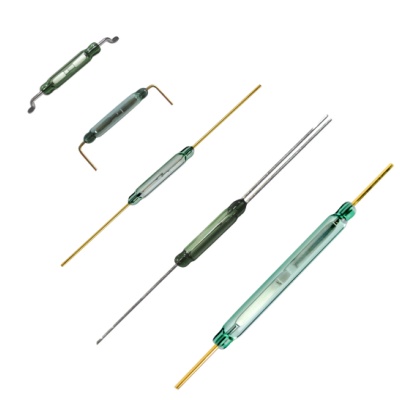
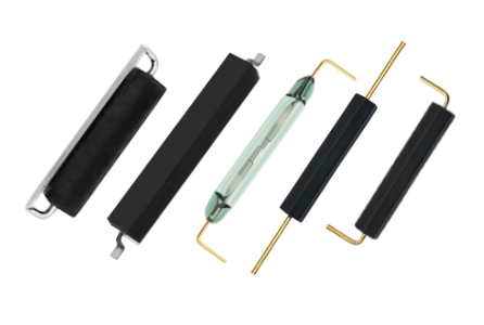
SIP Mould Reed Switch Series
When a magnet or coil creates a magnetic field that acts on the switch, both reeds of the reed switch become magnetized. An N pole is formed on the contact point of one of the reeds, and an S pole is formed on the contact point of the other reed. If the attractive force of the generated magnetic field causes the contacts to conduct, the circuit is closed. Once the magnetic field weakens to a certain extent, the reeds will separate again due to elastic force, which means the circuit is disconnected.
Line Mould Reed Switch
When a magnet or coil creates a magnetic field that acts on the switch, both reeds of the reed switch become magnetized. An N pole is formed on the contact point of one of the reeds, and an S pole is formed on the contact point of the other reed. If the attractive force of the generated magnetic field causes the contacts to conduct, the circuit is closed. Once the magnetic field weakens to a certain extent, the reeds will separate again due to elastic force, which means the circuit is disconnected.
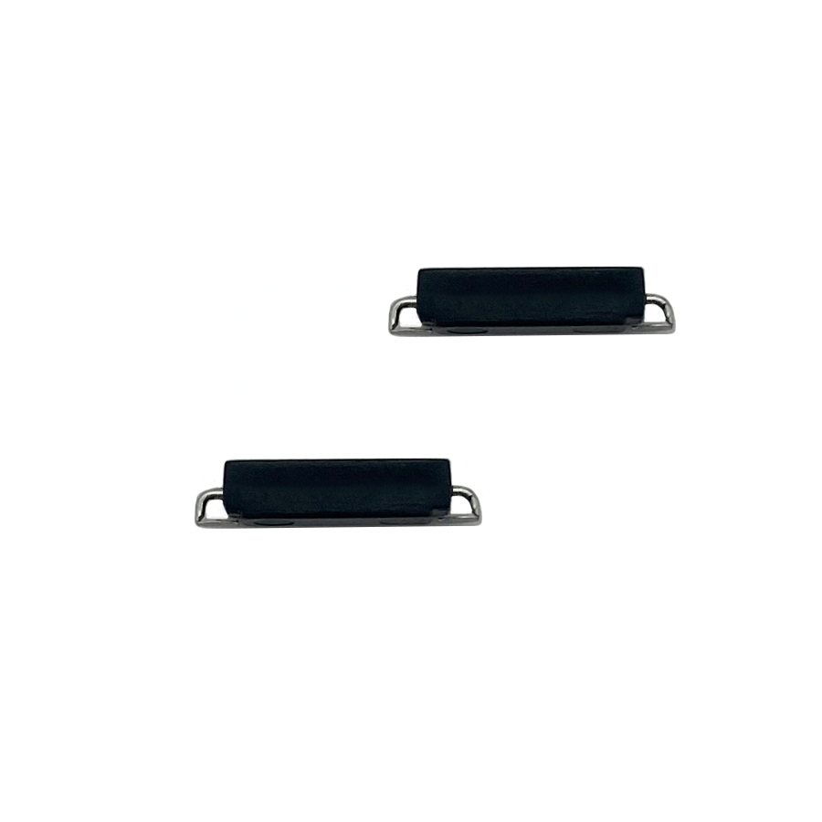
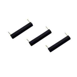
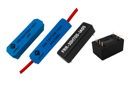
SMD Mould Reed Switch Series
When a magnet or coil creates a magnetic field that acts on the switch, both reeds of the reed switch become magnetized. An N pole is formed on the contact point of one of the reeds, and an S pole is formed on the contact point of the other reed. If the attractive force of the generated magnetic field causes the contacts to conduct, the circuit is closed. Once the magnetic field weakens to a certain extent, the reeds will separate again due to elastic force, which means the circuit is disconnected.
Reed Relay
A reed relay is a relay that uses a coil to generate a magnetic field to actuate a reed tube. It is a coil sensing device. Therefore, the characteristics of reed relays are small size, light weight, fast response speed, short bounce time and other characteristics. Mainly used in measurement equipment, communication equipment, security equipment, medical equipment, etc.
Industrial Relay
The main function of the relay is amplification. With a very small current, a circuit with a large power can be controlled, and the control range can also be expanded. When the signal reaches a certain value, the contacts can be switched simultaneously according to different forms of the contact group. Open and connect multiple circuits to achieve the purpose of automatic switching.
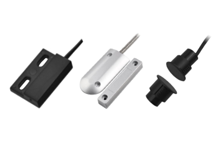
Magnetic Reed Type
Proximity switch/proximity sensors are widely used in various household appliances, security systems, access control systems, safety interlocks, position positioning, and equipment automation.
Hall Type
Hall type proximity switch is composed of a reed switch and a permanent magnet. They are individually enclosed in a plastic housing for protection and ease of installation.
SCR/MOSFET Type
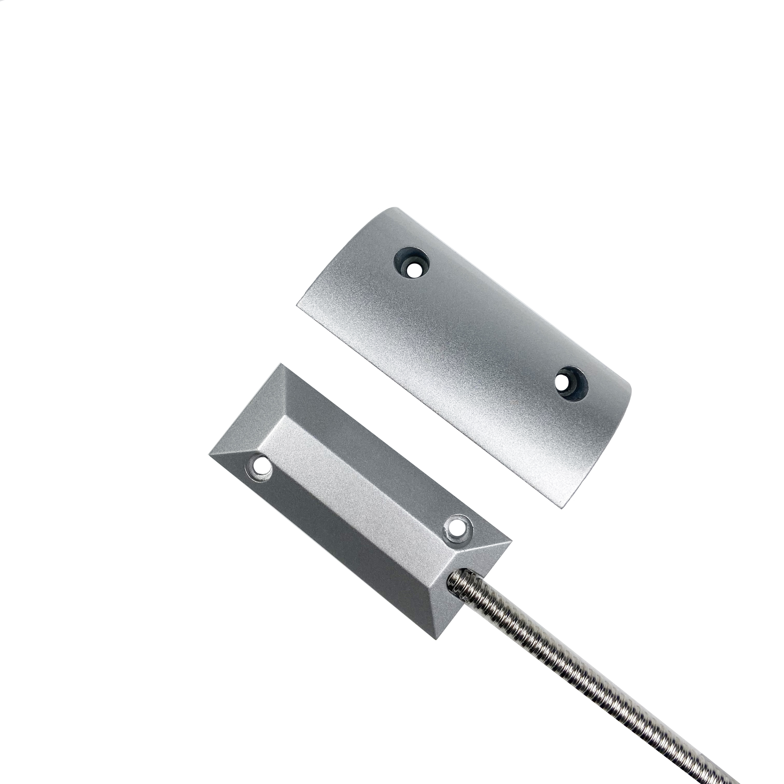
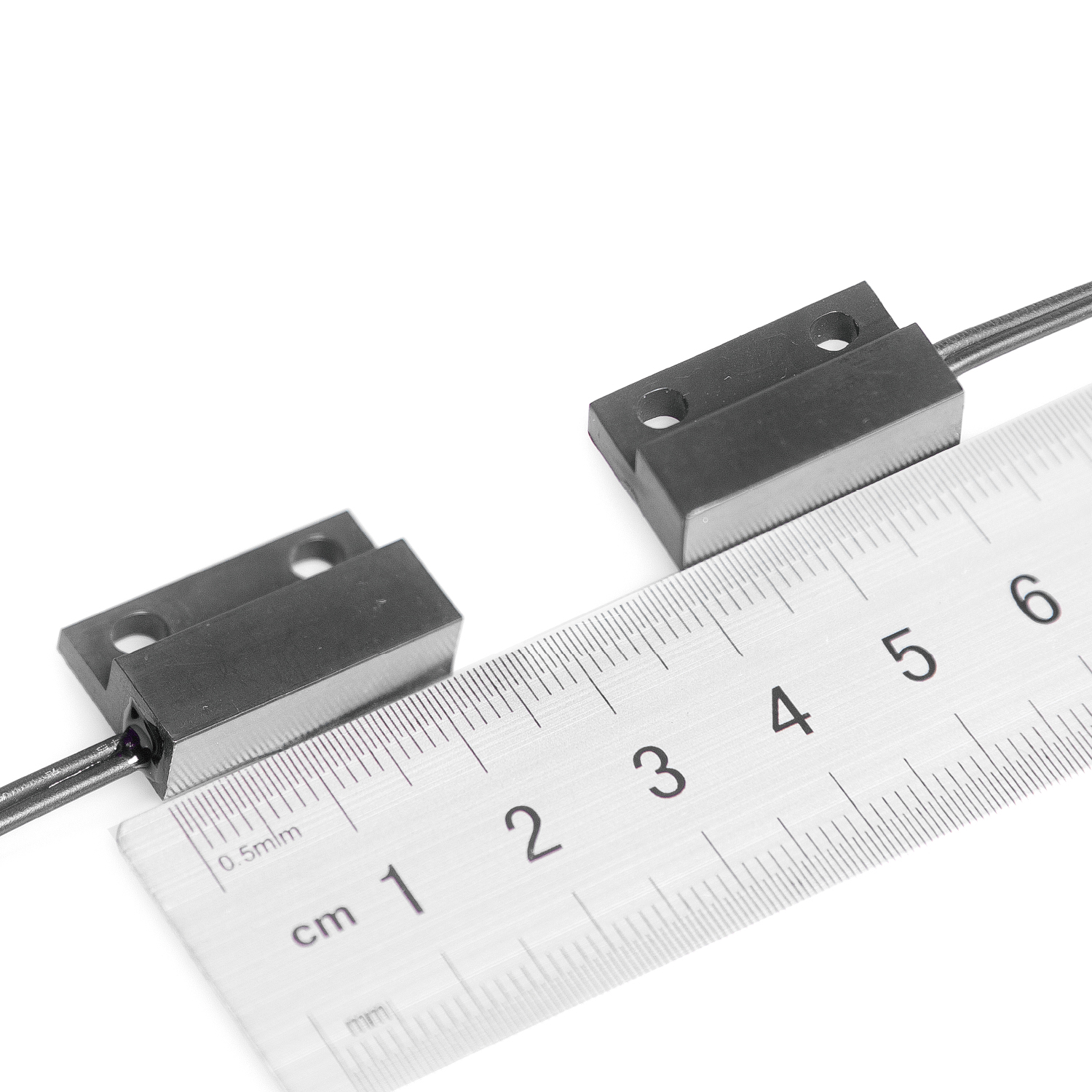
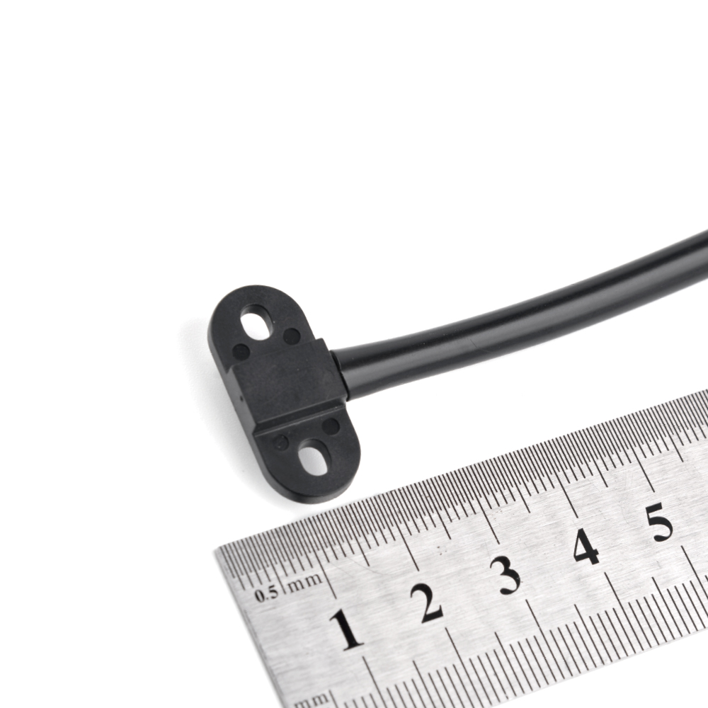
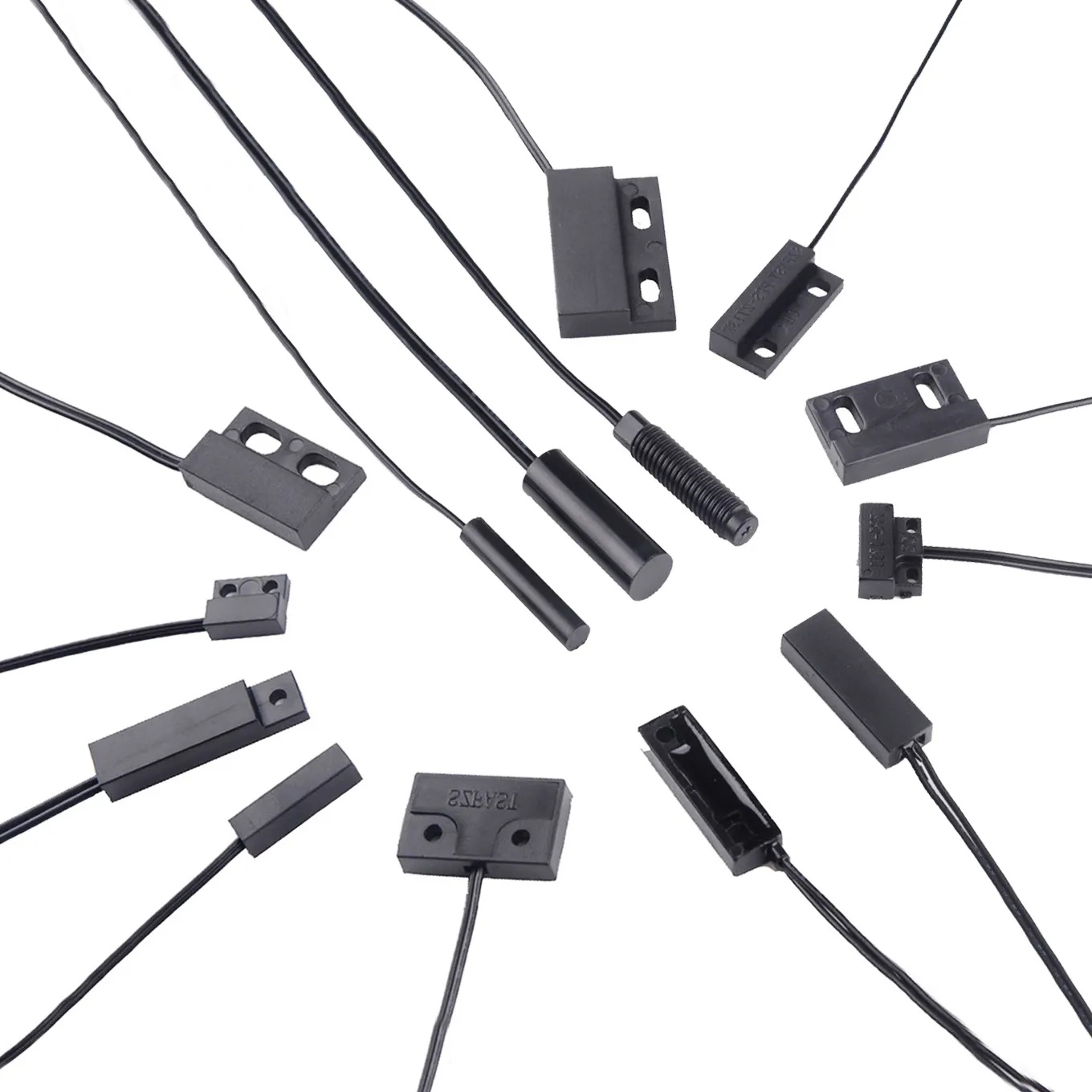
Magnetic Door Type
Proximity switches/proximity sensors are widely used in various household appliances, security systems, access control systems, safety interlocks, position positioning, and equipment automation.
Photoelectric Type
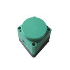
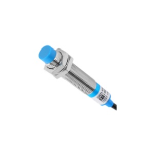
Inductive Type
Proximity switches/proximity sensors are therefore widely used in various household appliances, security systems, access control systems, safety interlocks, position positioning, and equipment automation.
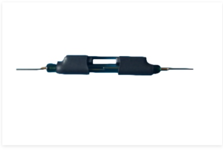
Dual-stable reed switch
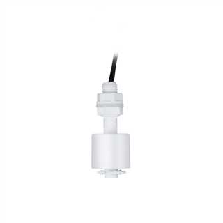
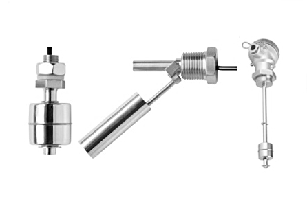
Plastic Materials
Widely used in the control of water tanks, compressors and pumps, household appliances, medical equipment, industrial braking, petrochemicals, food processing, electric power, public works, vehicles and ships, etc.
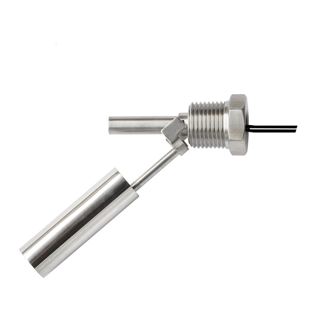
Stainless Steel Series
Widely used in the control of Water Tanks, Compressors and Pumps, Household Appliances, Industry Automation, Medical Equipment, Petrochemical Industry, Power, Food Processing, Public Engineering, Vehicles and Ships etc.
Photoelectric Liquid Level Sensor
FAST can provide customized wide-range sensors with up to 7 set points and lengths from 20mm to 2m. The valve stem and float can be made of stainless steel, PP, NBR and other materials.
Probe Level Sensor
Continuous Resistance Change
Widely used in the control of water tanks, compressors and pumps, household appliances, medical equipment, industrial automation, petrochemicals, food processing, electricity, public works, vehicles and ships, etc.
4-20mA Current output
Widely used in the control of water tanks, compressors and pumps, household appliances, medical equipment, industrial automation, petrochemicals, food processing, electricity, public works, vehicles and ships, etc.
0-5V Voltage output
Widely used in the control of water tanks, compressors and pumps, household appliances, medical equipment, industrial automation, petrochemicals, food processing, electricity, public works, vehicles and ships, etc.
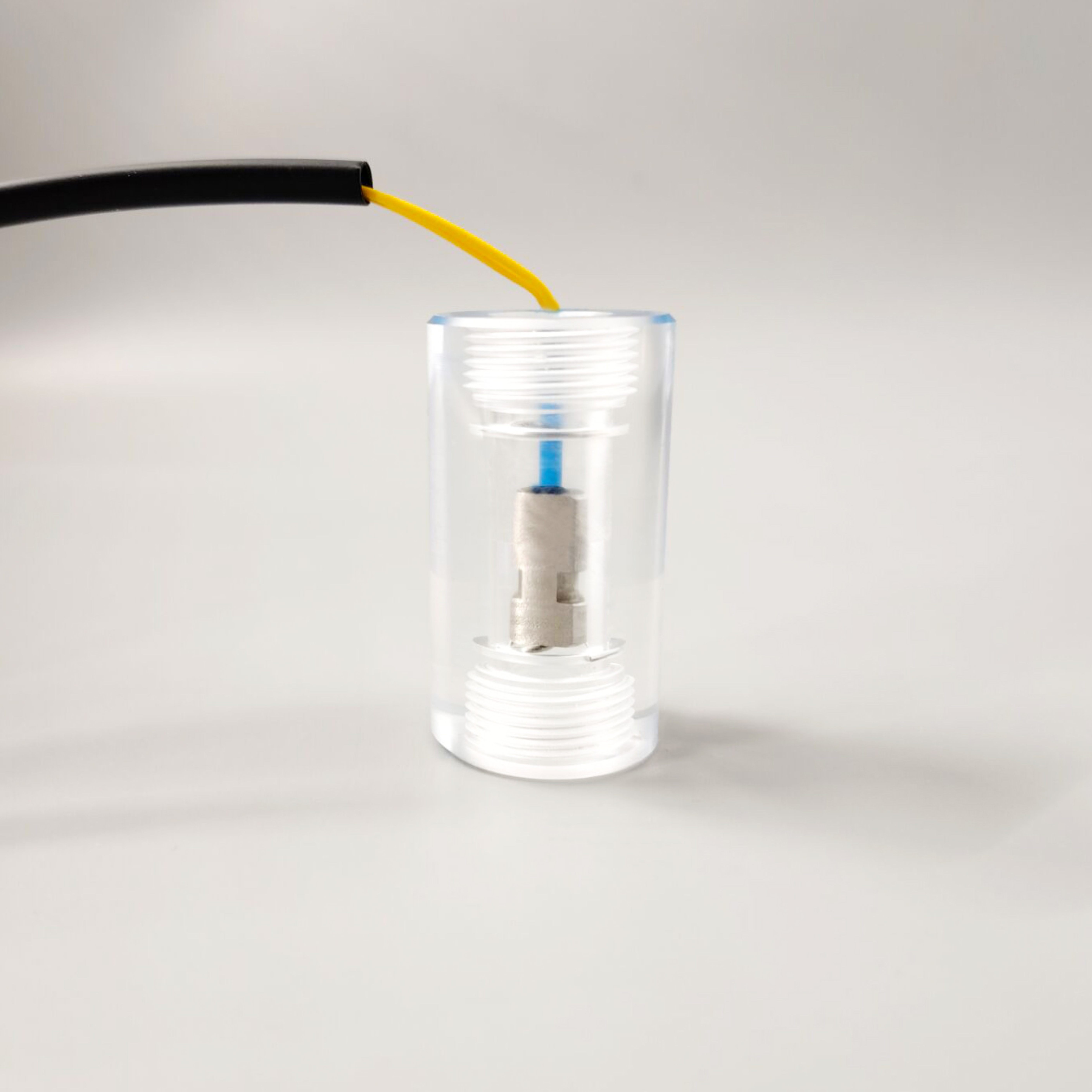
Plastic Flow Switch
All FAST flow sensors and flow switches are made of high-quality corrosion-resistant materials to ensure good performance in harsh environments. They are made from materials ranging from stainless steel to engineering plastics and are highly chemically compatible.
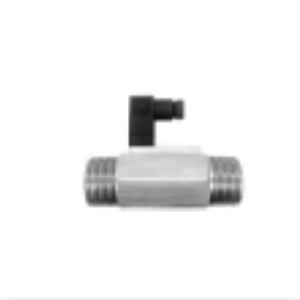
Stainless Steel Flow Switch
FAST flow sensors and flow switches are commonly used in applications such as rotating equipment, conveyors, gas sampling and distillation, water purification systems, welding machines, semiconductor equipment, chemical processing, machine tools and robotics.
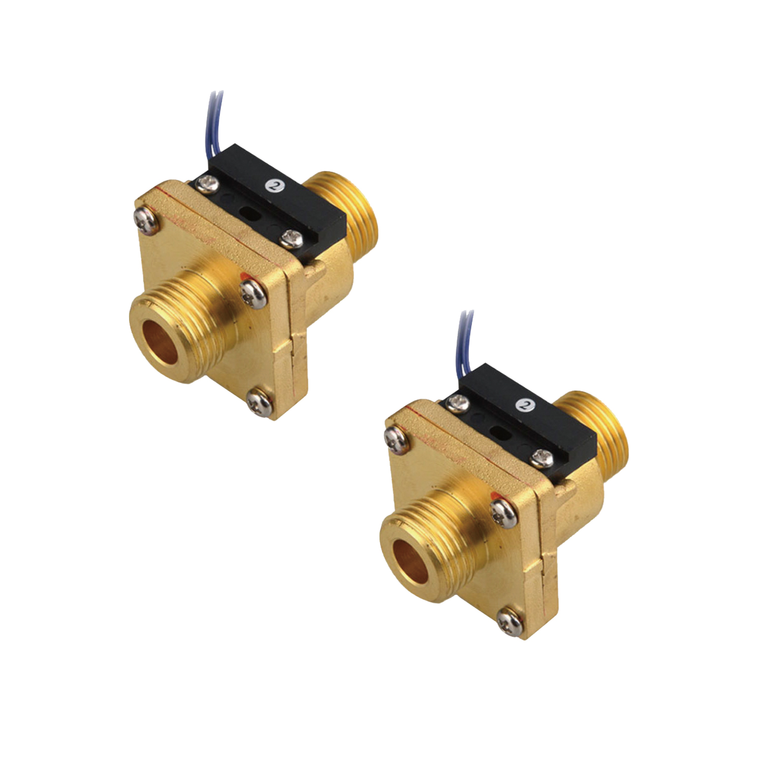
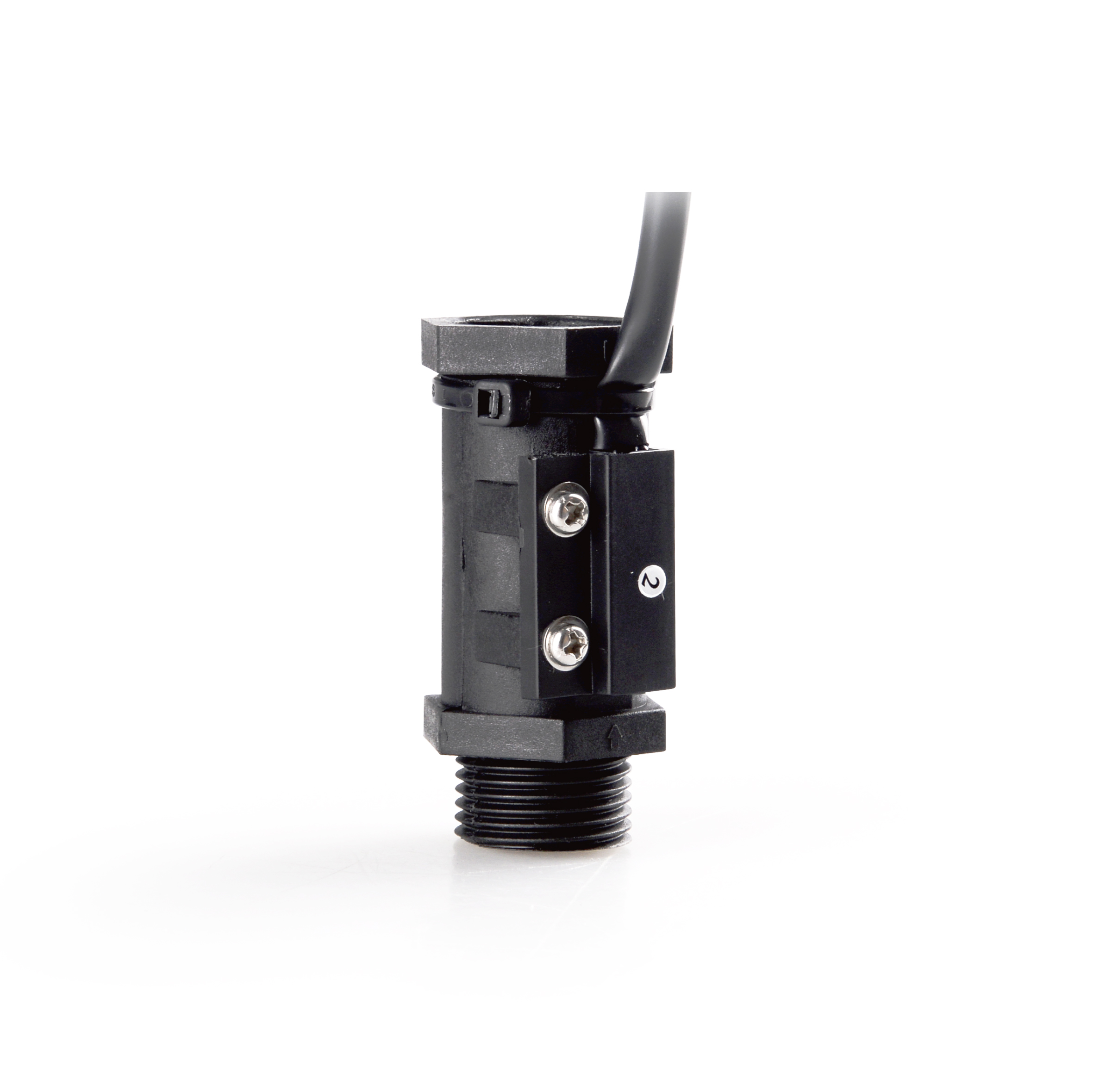
Brass Flow Switch
Gas/Air Flow Switch
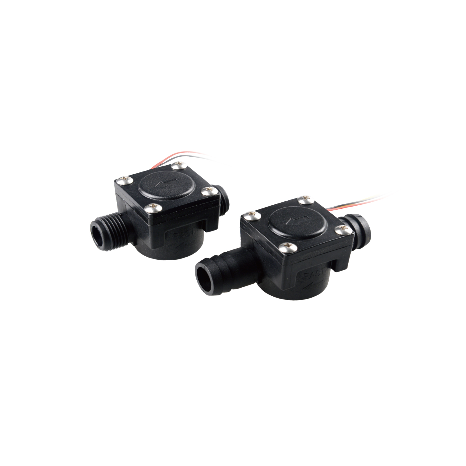
Plastic Flow Sensor
FAST flow sensors and flow switches are commonly used in applications such as rotating equipment, conveyors, gas sampling and distillation, water purification systems, welding machines, semiconductor equipment, chemical processing, machine tools and robotics.
Stainless Steel Flow Sensor
All FAST flow sensors and flow switches are made of high-quality corrosion-resistant materials to ensure good performance in harsh environments. They are made from materials ranging from stainless steel to engineering plastics and are highly chemically compatible.
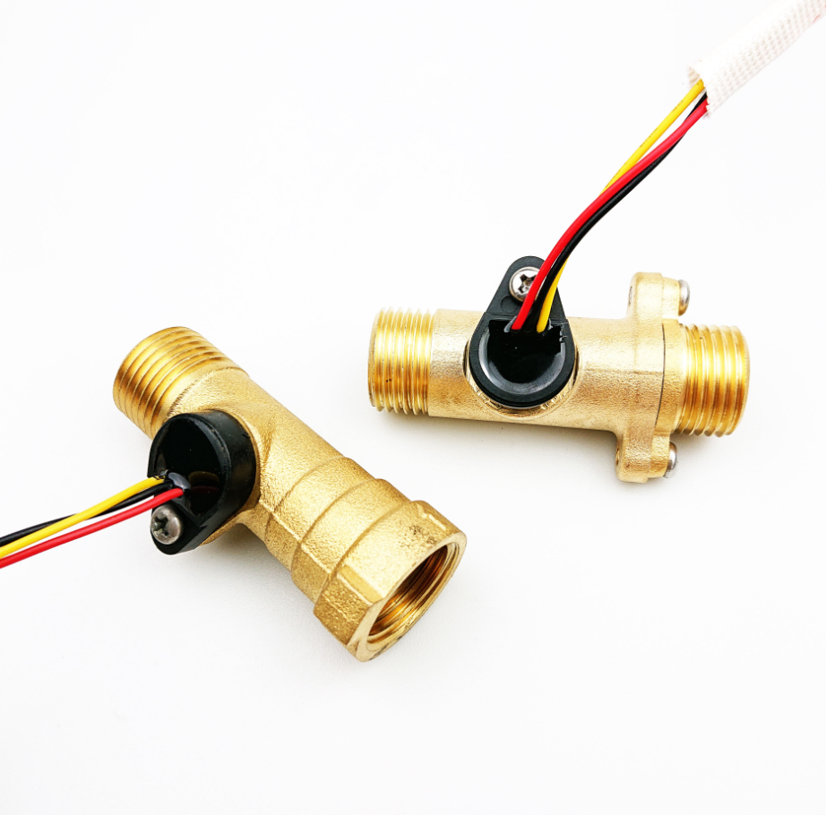
Brass Flow Sensor
Gas/Air Flow Sensor
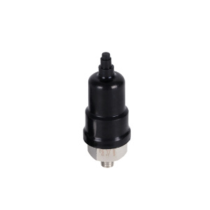
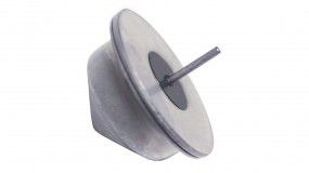
Plastic Pressure Switch
When the pressure in the system is higher or lower than the rated safety pressure, the disc in the sensor moves instantaneously, and the switch joint is turned on or off through the connecting rod. When the pressure drops or rises to the rated recovery value, The disc instantly resets and the switch automatically resets, or simply put, when the measured pressure exceeds the rated value, the free end of the elastic element is displaced, pushing the switch element directly or after comparison, changing the on-off state of the switch element, to achieve The purpose of controlling the measured pressure.
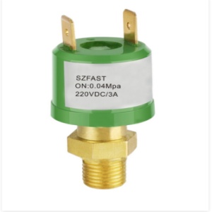
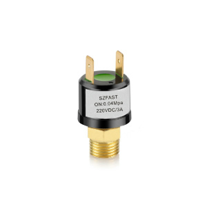
Brass Pressure Switch
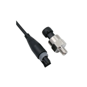
Stainless Steel Pressure Switch
When the pressure in the system is higher or lower than the rated safety pressure, the disc in the sensor moves instantaneously, and the switch connector is pushed on or off through the connecting guide rod. When the pressure drops to or rises to the rated recovery value, the disc resets instantly and the switch resets automatically. In simple terms, when the measured pressure exceeds the rated value, the free end of the elastic element is displaced, and the switch element is pushed directly or after comparison, changing the on-off state of the switch element to achieve the purpose of controlling the measured pressure.
Pressure Sensor
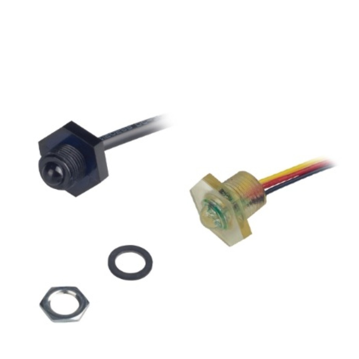
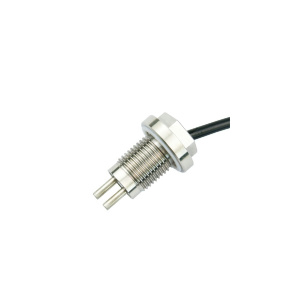
Probe Water Leak Detection Sensor
When a water leak occurs in a facility or equipment and water contacts both electrodes of the sensor at the same time, it will trigger the relay in the sensor to work and control the external alarm or water pump, solenoid valve and other equipment connected to it.
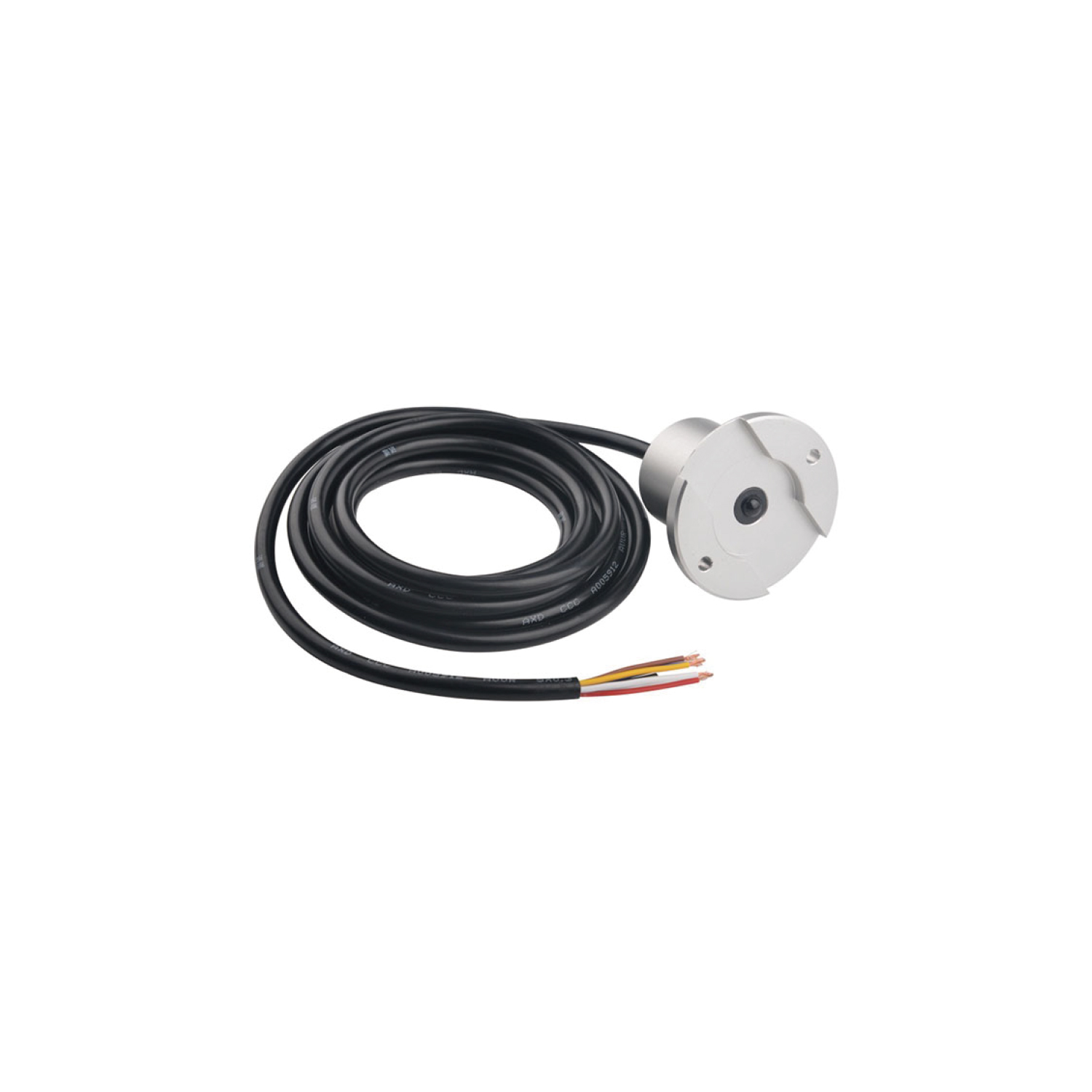
Photoelectric Water Leak Sensor
Temperature switch sensor
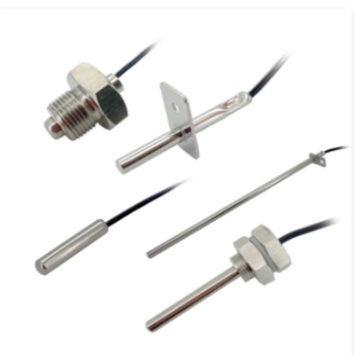
Temperature Sensor NTC
Temperature sensor products have stable performance, reliability and long life;NTC uses a temperature chip with a curve β value of ±1% and a resistance R value accuracy of ±1%. The outer casing is made of stainless steel 304 or nickel-plated copper, and is encapsulated with high-temperature epoxy resin. It can operate in harsh industrial environments;
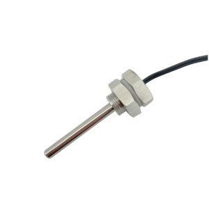
Temperature Sensor-PT100
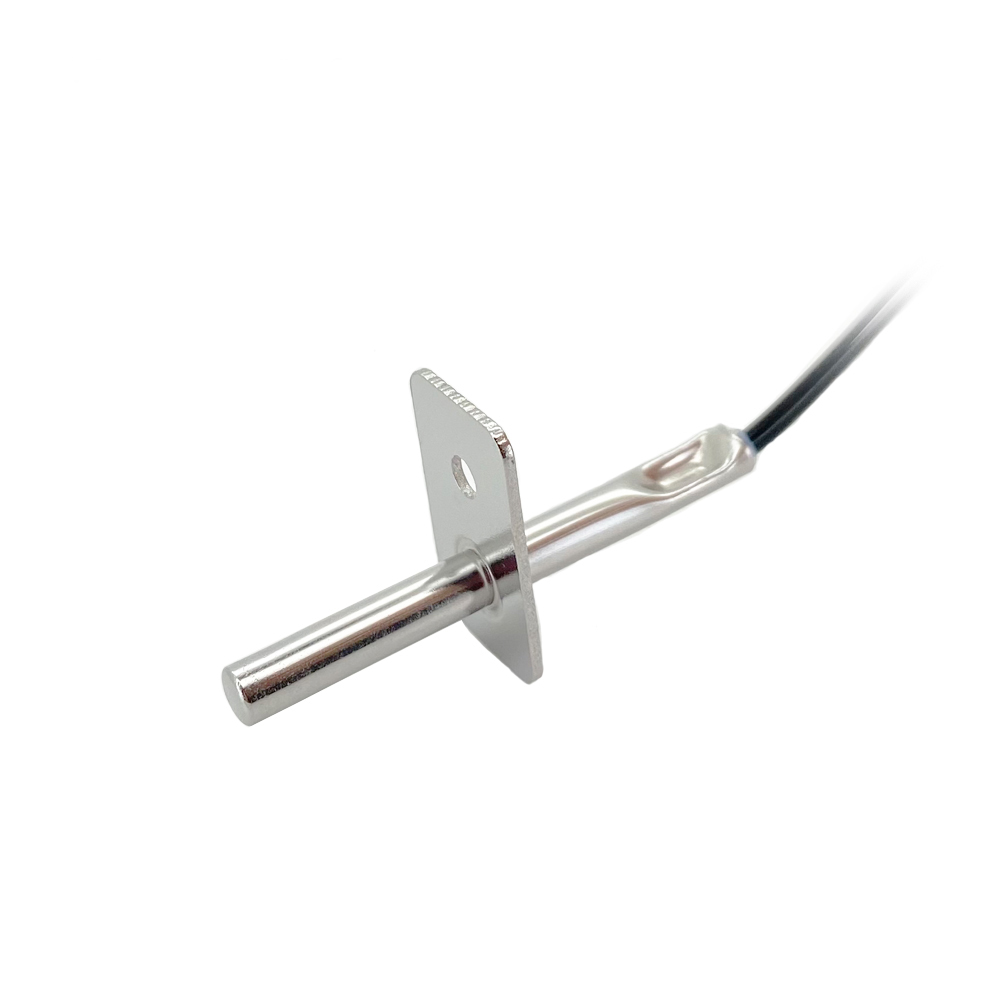
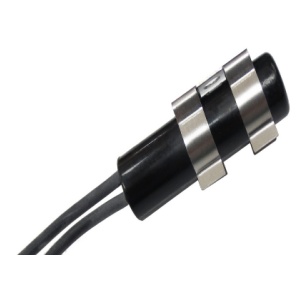
Reed Type Cylinder Magnetic Sensor
A variety of specifications are available, excellent material is wear-resistant, corrosion-resistant, not easy to damage, and long-lasting

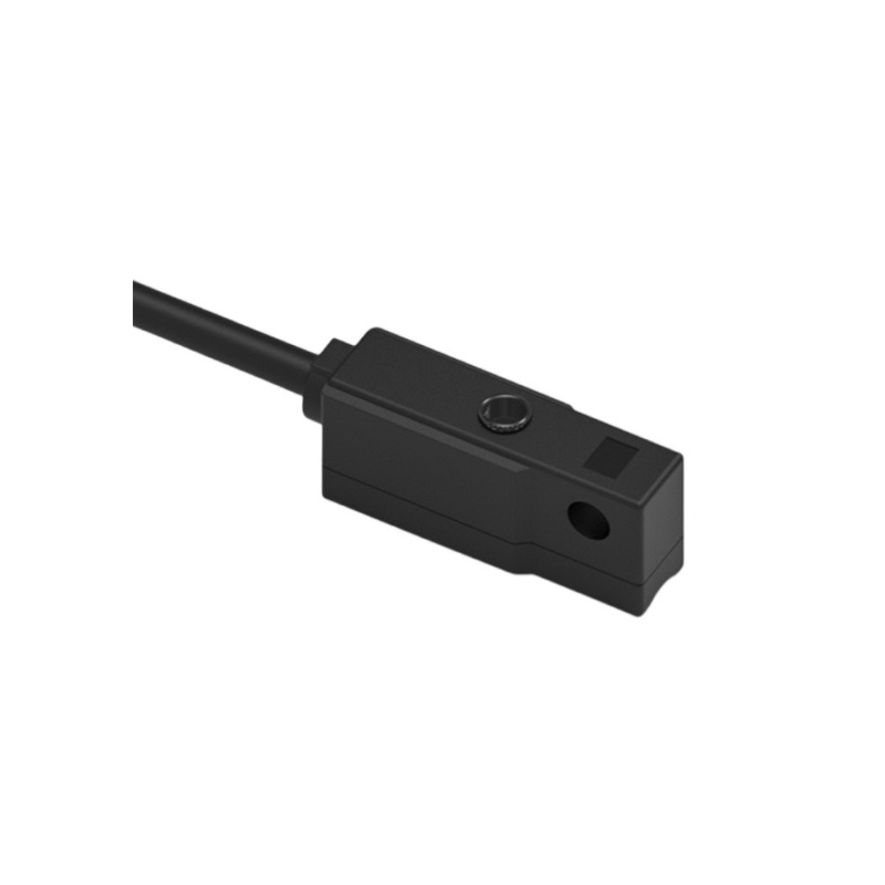
Hall Type Cylinder Magnetic Sensor
COTO RI
The advantages of compact structure, light weight, fast response time, long life and low cost. They are widely used in household appliances, industrial products, medical equipment, toys, fitness equipment, security, intelligent control, reed relays and other devices.
COMUS GC
Reed switches have contact types of normally open (Form A), normally closed (Form B) and normally closed normally open conversion (Form C). They are triggered by the magnetic field generated by a permanent magnet or a current-carrying coil.
STANDEX ORD
Reed switch consists of an elastic reed of magnetic material that is sealed in a glass tube filled with inert gas. The end faces of the magnetic sheets overlap but there is a certain gap in the middle, and the end face contacts are plated with a layer of precious metals (such as rhodium, ruthenium, etc.). Increases the stability of the switch and extends the service life of the machine.
DOLAM ZP
Reed switch consists of an elastic reed of magnetic material that is sealed in a glass tube filled with inert gas. The end faces of the magnetic sheets overlap but there is a certain gap in the middle, and the end face contacts are plated with a layer of precious metals (such as rhodium, ruthenium, etc.). Increases the stability of the switch and extends the service life of the machine.
ALEPH HYR
Reed switch consists of an elastic reed of magnetic material that is sealed in a glass tube filled with inert gas. The end faces of the magnetic sheets overlap but there is a certain gap in the middle, and the end face contacts are plated with a layer of precious metals (such as rhodium, ruthenium, etc.). Increases the stability of the switch and extends the service life of the machine.
LITTELFUSE MDSR
Reed switches have contact types of normally open (Form A), normally closed (Form B) and normally closed normally open conversion (Form C). They are triggered by the magnetic field generated by a permanent magnet or a current-carrying coil.
- FAST Mall
- Cases
- Contact Us

EN
 中文
中文 English
Products
PRODUCTS
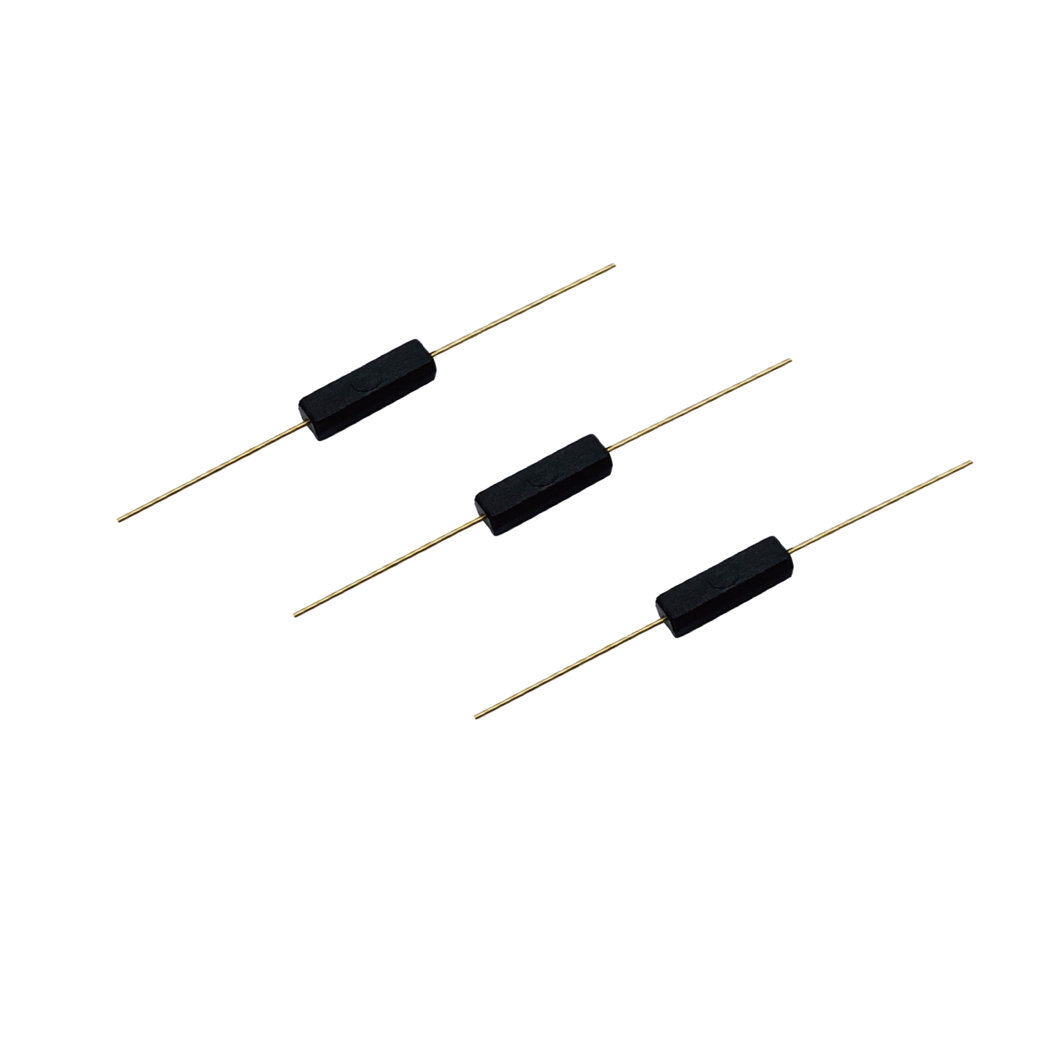
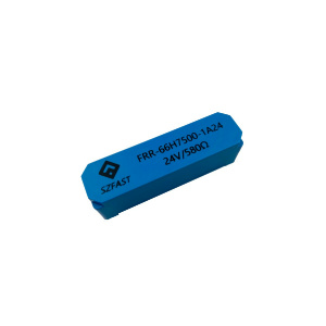
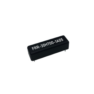
Mould Reed Switch
Built-in magnetic spring, quick alarm, convenient and easy to install, can be customized
Reed Relay
High sensitivity, high reliability, strong applicability, stable performance and long life
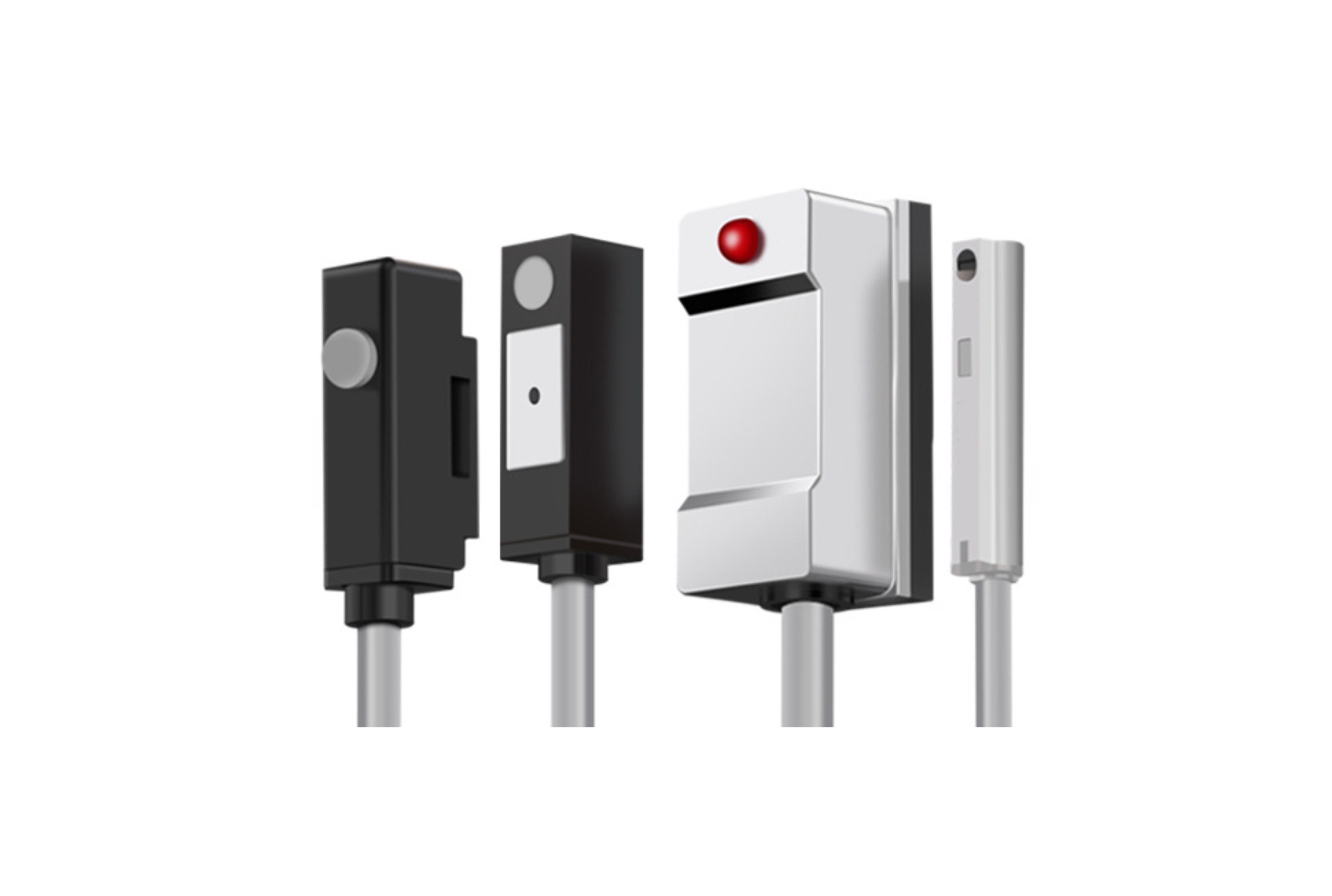
Proximity switch/sensor
Used for household appliances, sports equipment, automobiles, and industrial equipment, with high sensitivity and high repeatability accuracy.
Float Switch/Sensor
Used in manufacturing/automotive industry/smart appliances, strong durability, customizable.
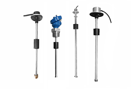
Liquid Level Sensor
Available in a variety of sizes, single ball single point, single ball multiple points, and hanging ball multiple points
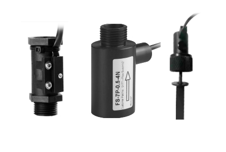
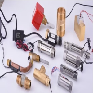
Flow Switch
Used in food production, refrigeration equipment, water purification treatment, power equipment, petrochemical industry, with excellent performance.
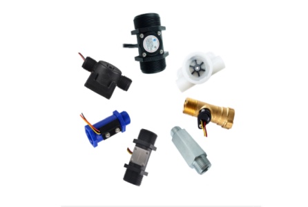
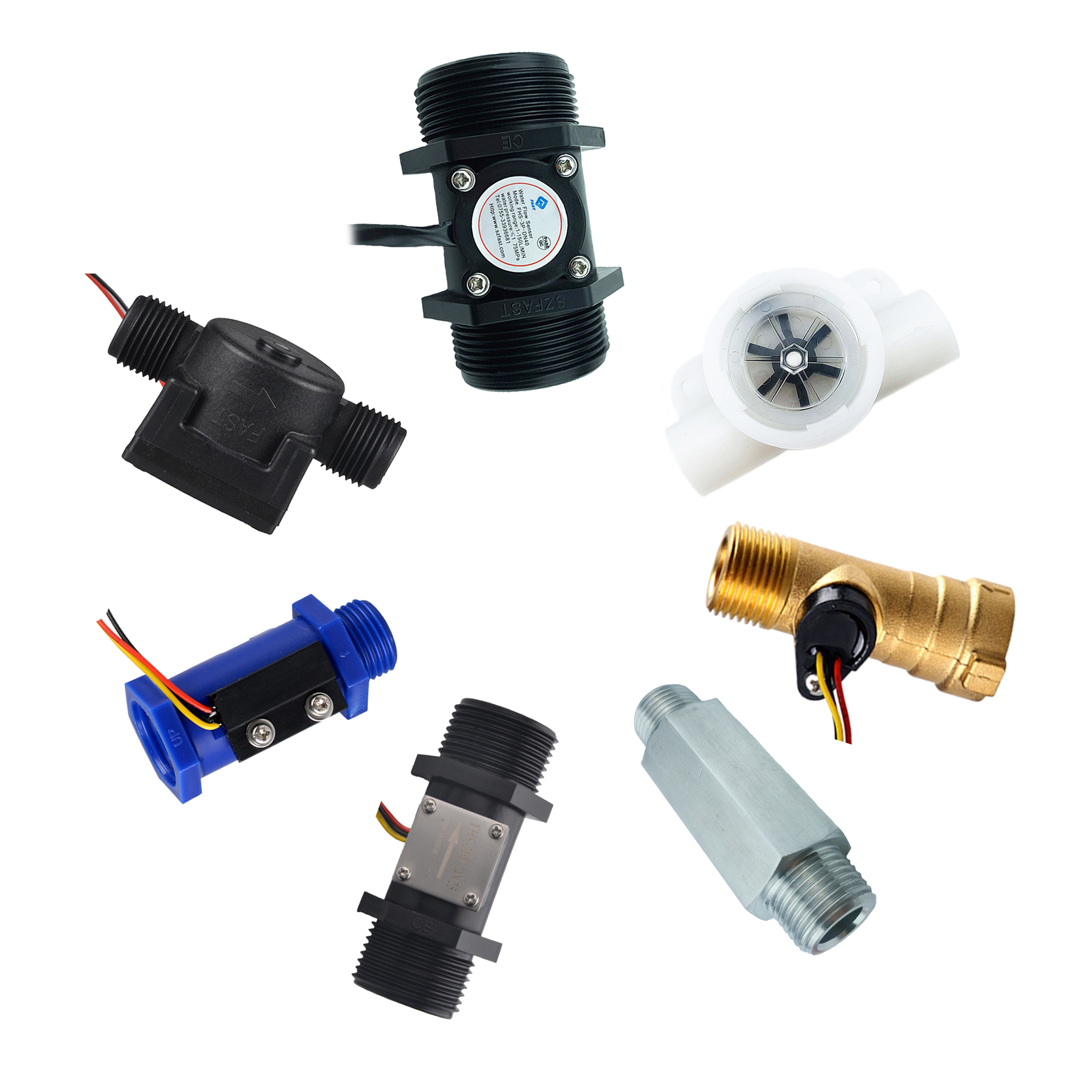
Flow Sensor
Flow sensors display and flow accumulation calculation. It can be used as a flow switch and also as a flow meter for flow accumulation calculation.
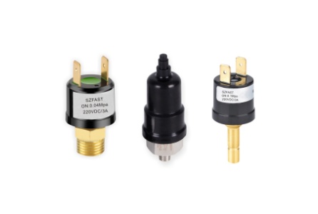
Pressure Switch
Applied in various industrial fields,
Water Detection/Leak Sensor
Fast detection speed, wide monitoring range, sensitive reaction, good durability, accurate positioning
Tilt switch
Tilt switch is suitable for food, silica sand, rock, small particles, wood, soil, rubber, metal, processed materials, coal, mixed oil, soil, resin, limestone, particles, malt etc
Acceleration&Shock Switch
The products can be integrated into various electronic devices and systems, durable, directional and fast response
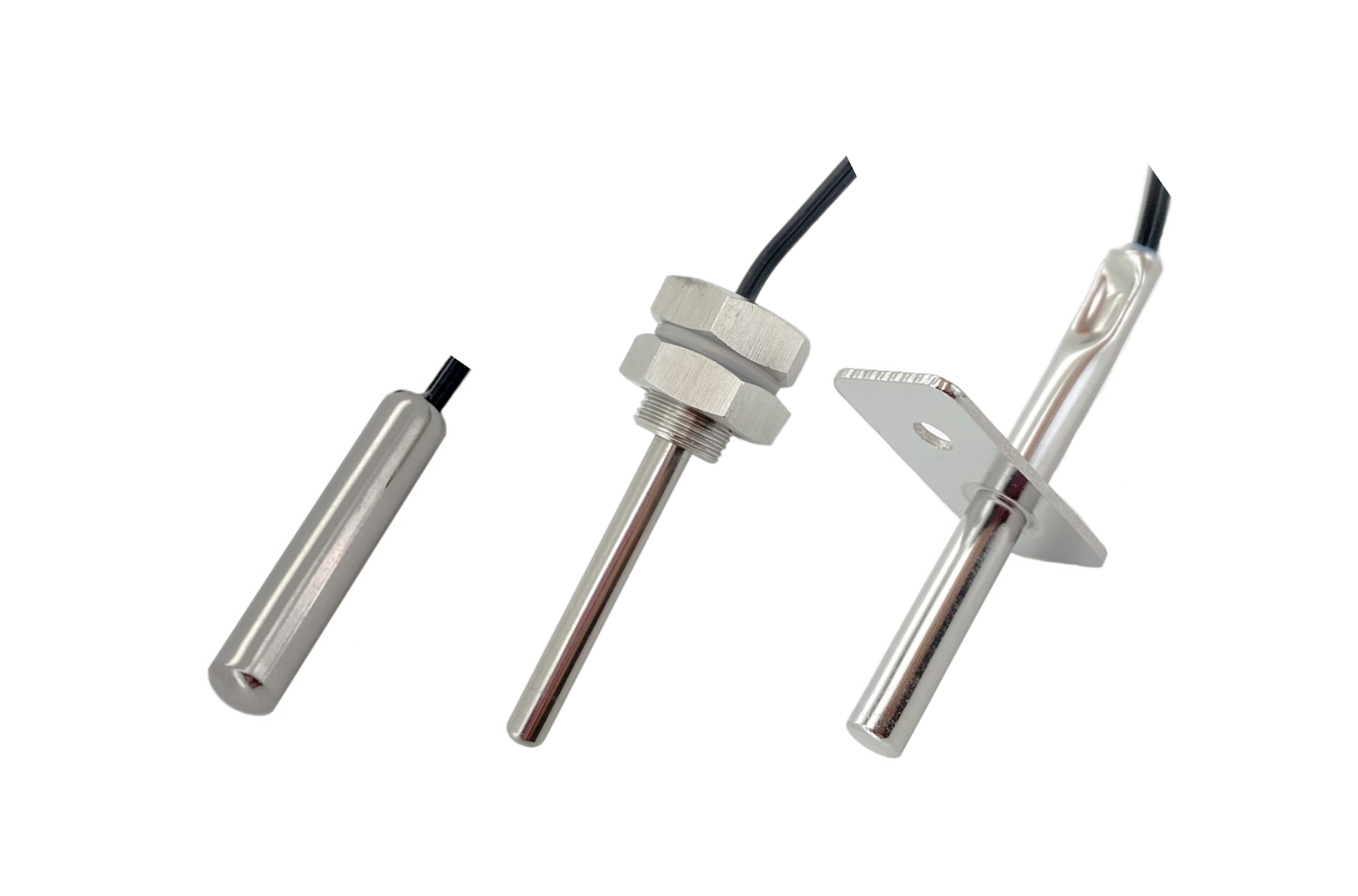
Temperature Sensor
High accuracy, high resolution, strong anti-interference, suitable for fast response or high-precision measurement scenarios
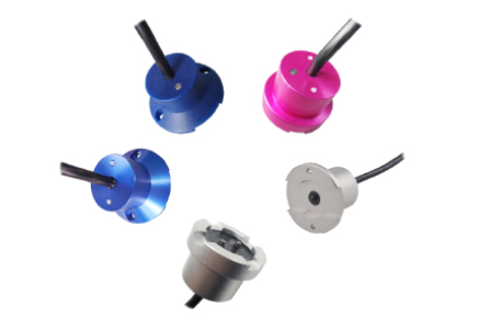
Cylinder Magnetic Sensor
Non-contact detection, high reliability, fast response speed, widely used in automatic control systems
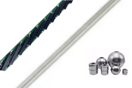
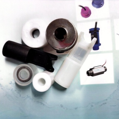
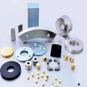
Component Parts of Sensors
Sensor components include floats, magnets, reed PCB components and kits made of different materials.
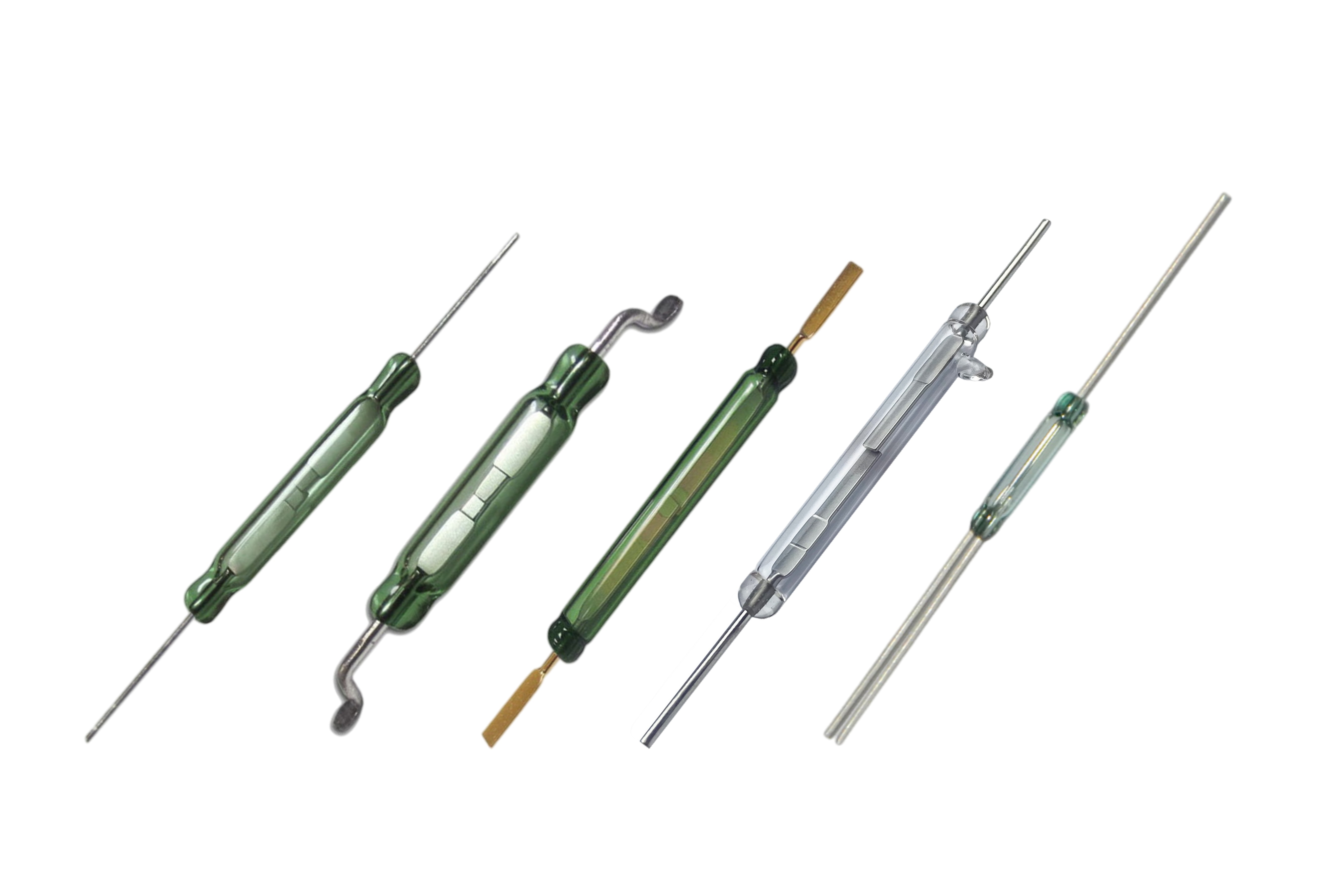
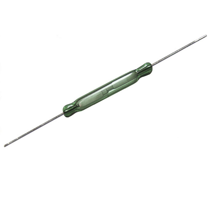
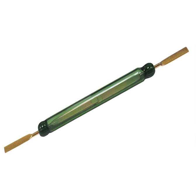
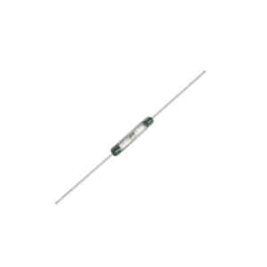
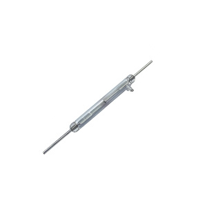
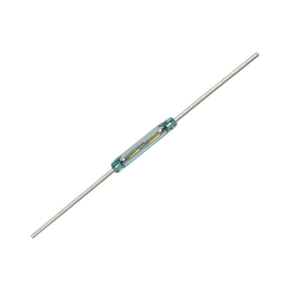
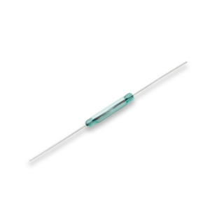
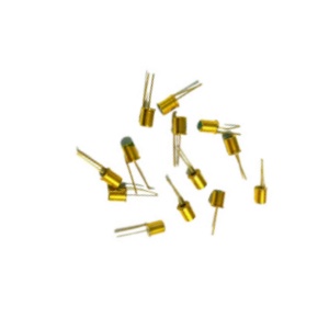
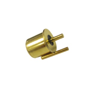
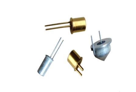
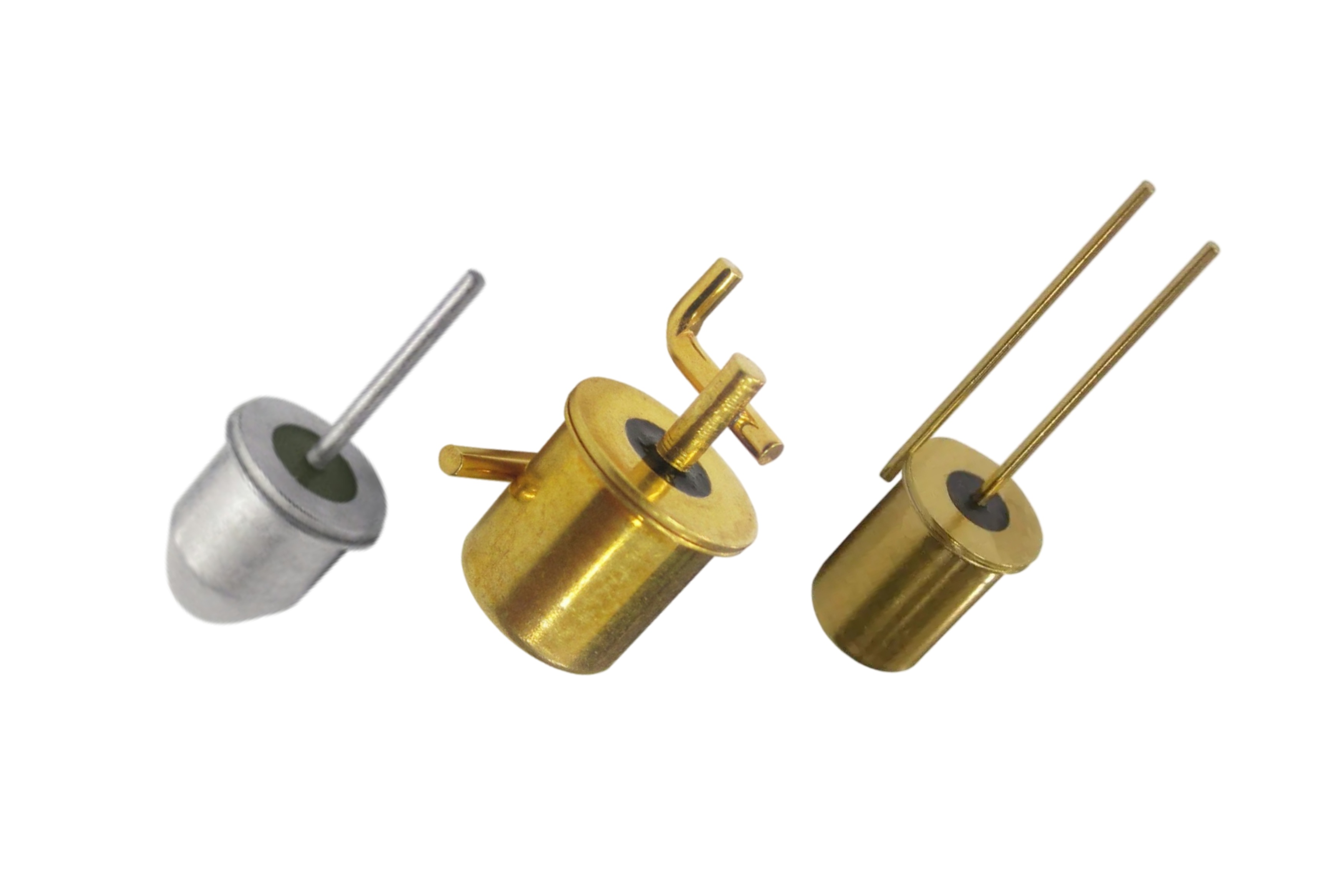
Reed Switch
Widely used in transistors and integrated circuits, it has a compact structure, light weight, and long lifespan.
FAST ELECTRIC LIMITED. Copyright © 2024 All Rights reserved.